
NFPA 96: Commercial Kitchen Ventilation
Ventilation control and fire protection requirements for commercial cooking operations
Last updated: July 21, 2026
Overview
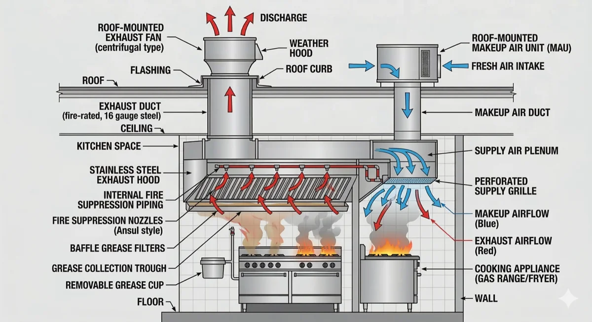
NFPA 96 is the standard for ventilation control and fire protection of commercial cooking operations. It addresses the design, installation, operation, inspection, and maintenance of all components in commercial kitchen exhaust systems including hoods, ducts, fans, and fire suppression equipment.
NFPA 96 (2024) is the current published edition, issued in April 2023. Your local authority having jurisdiction (AHJ) may still enforce an older adopted edition such as 2017 or 2021. Always confirm which edition applies before designing or installing a system.
Notable 2024-edition changes versus 2021 include an expanded chapter on mobile and temporary cooking operations (food trucks, ghost-kitchen pods, LP-gas alignment with NFPA 58), clarified responsibility for inspection, testing, and maintenance, and revised label and inspection-tag requirements. A successor edition is moving through the NFPA Annual 2026 revision cycle and is expected to publish as the 2027 edition. Check NFPA’s document page for current status before citing an edition year.
NFPA 96 works in conjunction with UL 300 for suppression system requirements and local mechanical codes. The full standard text is available through the NFPA free access page.
Quick Reference
Common plan-check values for NFPA 96 commercial kitchen exhaust systems.
| Requirement | Value |
|---|---|
| Duct velocity | 500–2,500 fpm |
| Duct slope | ≥ 1/4 in/ft; ≥ 1 in/ft where horizontal runs exceed 75 ft |
| Minimum thickness (carbon steel) | ≥ 0.055 in (16 ga) |
| Minimum thickness (stainless steel) | ≥ 0.044 in (18 ga) |
| Roof termination | Commonly 24–40 in above roof surface (varies by AHJ) |
| Cleaning frequency | Monthly to annual by cooking type and volume |
Duct velocity
500–2,500 fpm
Duct slope
≥ 1/4 in/ft; ≥ 1 in/ft where horizontal runs exceed 75 ft
Min thickness (carbon steel)
≥ 0.055 in (16 ga)
Min thickness (stainless steel)
≥ 0.044 in (18 ga)
Roof termination
Commonly 24–40 in above roof surface (varies by AHJ)
Cleaning frequency
Monthly to annual by cooking type and volume
Source: US Made Supply plan-check reference guide
Requirements vary by AHJ and adopted code edition. Verify locally before design or installation.
The values in this guide are drawn from publicly available plan-check guidance including LA Mechanical Code, Alameda County, Huntington Beach, and Gwinnett County. Your local AHJ may enforce different values. Always verify requirements with the jurisdiction where your project is located.
Firestop for Grease-Duct & Hood Penetrations
Intumescent firestop products for NFPA 96-compliant sealing of duct, pipe, and service openings through fire-rated assemblies.


Hood Requirements
NFPA 96 specifies detailed requirements for exhaust hood design and installation:
- Type I Hoods: Required for cooking equipment producing grease-laden vapors
- Type II Hoods: For equipment producing heat and steam but no grease vapors
- Overhang (IMC 507.4.1): Canopy-type hoods overhang at least 6 inches beyond the equipment on all open sides. NFPA 96 5.2 is performance-based (sized and configured to capture and remove); the 6 inch dimension comes from the mechanical code
- Hood Height (IMC 507.4.1): Maximum 4 feet between the front lower lip of a canopy-type hood and the cooking surface — also a mechanical code dimension, not an NFPA 96 prescriptive limit
- Exhaust Rate: Minimum airflow rates based on hood type and cooking equipment
- Grease Filters (6.1): Listed grease removal devices — baffle-type filters listed to UL 1046 — readily removable for cleaning. Standalone mesh filters are not permitted for grease-laden vapor; mesh is acceptable only where it is evaluated as part of a listed hood or listed together with a primary filter
- Materials (5.1.1): Steel minimum 0.043 in (No. 18 MSG) or stainless steel minimum 0.037 in (No. 20 MSG)
Makeup Air Requirements
Commercial kitchen exhaust hoods remove large volumes of air from the building. That air must be replaced — this replacement air is called makeup air. Without adequate makeup air, the building goes under negative pressure, causing a cascade of operational and safety problems.
NFPA 96 Section 8.3.1 requires that replacement (makeup) air be provided to prevent the building’s negative pressure from exceeding 0.02 inches water column (in. w.c.) when the exhaust system is operating. The International Mechanical Code (IMC) Section 508.1 further requires that makeup air systems be automatically controlled to start and stop with the exhaust system.
Symptoms of Inadequate Makeup Air
These are the most common signs that a commercial kitchen does not have enough makeup air. If your restaurant or kitchen experiences any of these, the exhaust system is likely pulling the space into negative pressure:
- Doors hard to open: Entry and service doors are difficult to push open or slam shut on their own due to the pressure differential across the door
- Pilot light outages: Gas appliance pilot lights blow out repeatedly as air is drawn across burners toward the exhaust hood
- Poor hood capture: Smoke and cooking vapors spill out from under the hood instead of being drawn into the exhaust system
- CO backdrafting: Combustion gases from water heaters or furnaces are pulled back into the building instead of venting properly — a serious safety hazard
- Excessive noise: Whistling or rushing air sounds at doors, windows, and gaps in the building envelope
- Grease filter bypass: Air velocity through filters is uneven, causing grease to deposit in the ductwork instead of on the filters
Makeup Air Sizing
A general rule of thumb is to replace approximately 90% of the exhausted air volume with conditioned or tempered makeup air. The remaining 10% comes from transfer air through the building. Key design parameters:
| Parameter | Typical Value |
|---|---|
| Replacement air ratio | ~90% of exhaust volume |
| Supply temperature | Within 10°F of room temperature (per IMC) |
| Delivery method | Short-circuit (at hood), perimeter diffusers, or transfer air |
| Controls | Interlocked with exhaust fan — auto start/stop |
| DCKV compatibility | Variable makeup air matched to demand-controlled kitchen ventilation |
Replacement air ratio
~90% of exhaust volume
Supply temperature
Within 10°F of room temp (per IMC)
Delivery method
Short-circuit, perimeter diffusers, or transfer air
Controls
Interlocked with exhaust fan — auto start/stop
DCKV compatibility
Variable makeup air matched to demand-controlled ventilation
Demand-Controlled Kitchen Ventilation (DCKV)
DCKV systems use sensors to modulate exhaust fan speed and makeup air volume based on actual cooking activity. When cooking load is light, the system reduces airflow— saving 30–50% on HVAC energy. ASHRAE 90.1 Section 6.5.7.1.4 triggers kitchen exhaust energy requirements above 5,000 cfm of total hood exhaust; DCKV is one of the allowed compliance paths, not the only one. ASHRAE Standard 154 (Ventilation for Commercial Cooking Operations) is the design reference for capture and containment. Many utility companies offer rebates for DCKV retrofits.
Makeup air requirements and delivery methods are enforced by the local AHJ under the adopted mechanical code. NFPA 96 sets the negative pressure limit; the IMC and local amendments define the system design requirements. Always verify with the jurisdiction where your project is located.
Duct Velocity Requirements
Common mechanical code plan-check guidance specifies grease duct air velocity between 500 fpm minimum and 2,500 fpm maximum. These values appear in the LA Mechanical Plan Check Correction List and the Alameda County Mechanical Exhaust Ventilation Guideline.
NFPA 96 itself does not state “500 fpm” as a prescriptive minimum — that figure comes from mechanical code plan-check guidance adopted by jurisdictions like LA County, Alameda County, and Huntington Beach. The 2,500 fpm maximum similarly originates from plan-check guidance, not from NFPA 96 text. Always confirm which values your local AHJ enforces.
| Application | Velocity Guidance |
|---|---|
| Grease exhaust duct (Type I hood) | 500–2,500 fpm |
| Type II hood (heat/steam only) | Per mechanical code; grease duct minimums do not apply |
Why the Velocity Range Matters
The 500–2,500 fpm range exists for practical reasons tied to grease behavior, noise, and equipment longevity:
- Below 500 fpm: Grease-laden air moves too slowly and grease condenses on duct walls instead of being carried to the exhaust fan. This increases fire load inside the duct and makes cleaning harder and more frequent
- Above 2,500 fpm: Turbulence increases, noise becomes objectionable in occupied spaces, grease filters load unevenly, and vibration fatigue on duct joints accelerates — particularly at transitions and elbows
- Practical sweet spot: Most commercial kitchen installations target 1,200–1,800 fpm. This range provides reliable grease transport with acceptable noise and reasonable fan energy consumption
How Duct Velocity Relates to Duct Sizing
Velocity is a function of airflow volume and duct cross-sectional area: Velocity (fpm) = CFM ÷ Duct Area (sq ft). An undersized duct pushes velocity too high (noise, turbulence). An oversized duct drops velocity too low (grease accumulation). Getting the duct size right at design is the single most important factor in maintaining velocity within the acceptable range.
| Duct Size | Cross-Section (sq ft) | CFM at 500 fpm | CFM at 1,500 fpm | CFM at 2,500 fpm |
|---|---|---|---|---|
| 10″ round | 0.55 | 273 | 818 | 1,364 |
| 12″ round | 0.79 | 393 | 1,178 | 1,963 |
| 14″ round | 1.07 | 535 | 1,604 | 2,674 |
| 16″ round | 1.40 | 698 | 2,094 | 3,491 |
| 18″ × 18″ rect | 2.25 | 1,125 | 3,375 | 5,625 |
| 24″ × 24″ rect | 4.00 | 2,000 | 6,000 | 10,000 |
Use this table to verify that a given duct size keeps velocity within the 500–2,500 fpm range for the system’s design CFM.
How Duct Velocity Is Measured in the Field
Duct velocity is measured during commissioning (TAB), after major cleaning, or when troubleshooting airflow complaints. Three common methods:
- Pitot tube traverse: The standard method for round and rectangular ducts per AMCA 203 and ASHRAE 111. A pitot tube connected to a manometer measures velocity pressure at multiple points across the duct cross-section, then results are averaged. Most accurate method, but requires access ports and trained technicians
- Hot-wire anemometer: Inserted at access panel openings to read velocity directly. Faster than a pitot traverse but less accurate for full-duct averages because it measures a single point. Useful for spot-checking
- Calculated from fan CFM and duct area: If the fan nameplate CFM is known and the duct dimensions are measured, velocity can be estimated as CFM ÷ duct area. This “shortcut” method assumes the fan is delivering nameplate CFM — which may not be true if the system has aged, filters are loaded, or duct has accumulated grease
When measurement is required: TAB commissioning of new installations, post-cleaning verification when airflow complaints exist, troubleshooting smoke capture problems, and whenever the system has been modified (new branches, damper changes, fan replacement).
Common Reasons Duct Velocity Drifts Out of Range
A system that was in spec at commissioning can drift out of range within months. Common causes:
- Grease buildup reducing effective duct area: As grease accumulates on duct walls, the effective cross-section shrinks. Velocity at the narrowed point increases, but total airflow (CFM) drops because the system’s static pressure rises
- Fan belt wear or slippage: Belt-driven fans lose RPM as belts stretch and wear, reducing delivered CFM and dropping velocity below the minimum
- Filter loading: Grease-laden filters increase resistance across the hood, reducing airflow through the duct and lowering velocity
- Makeup air imbalance: If the makeup air system fails or is undersized, the building goes under negative pressure and the exhaust fan must work against higher static, reducing actual CFM
- Duct modifications after commissioning: Adding branches, changing damper positions, or connecting additional hoods to an existing duct run changes the system’s airflow distribution
What this means in practice: periodic airflow verification — not just visual duct inspection — is needed to confirm the system is still operating within the design velocity range.
Edition Differences and the 1,500 fpm Question
Searches for “NFPA 96 2021 minimum duct velocity” and “current NFPA 96 minimum duct velocity 2023” are common because there is genuine confusion about where velocity requirements originate.
- NFPA 96 (2024) is the current edition, published in 2023. Most AHJs still enforce the 2017 or 2021 adopted editions
- NFPA 96 does not prescribe a specific minimum or maximum duct velocity in its text. The 500–2,500 fpm range comes from mechanical code plan-check guidance adopted by individual jurisdictions
- Some older references and training materials cite 1,500 fpm as a minimum. This value appears in certain legacy plan-check documents and mechanical engineering references, but is not universally adopted
- The velocity requirement does not change between NFPA 96 editions because NFPA 96 does not set it — the local mechanical code and AHJ plan-check guidance set it
Bottom line: Always check with your AHJ for the adopted code edition and the specific velocity values they enforce. The 500–2,500 fpm range is the most common plan-check standard, but your jurisdiction may differ.
Duct Slope Requirements
Grease ducts must slope at a minimum of 1/4 inch per linear foot toward the hood or an approved grease reservoir. This slope prevents grease from pooling inside horizontal runs.
Critical exception: Where horizontal duct runs exceed 75 feet, the slope increases to 1 inch per linear foot. This is in NFPA 96 itself (2021 and 2024), stated as a 2 percent slope up to 75 feet and 8 percent beyond 75 feet, and it is echoed in the Alameda County Mechanical Exhaust Ventilation Guideline and similar jurisdictional documents.
- Standard slope: ≥ 1/4 in/ft toward hood or grease reservoir
- Long horizontal runs (>75 ft): ≥ 1 in/ft (8 percent) per NFPA 96
- Cleanouts: Required at each change in slope direction
- Listed duct systems: Factory-built grease duct systems may have alternative slope allowances per their listing — verify with the product listing and your AHJ
Why Slope Matters for Fire Safety and Cleaning
Slope drains liquid grease toward the hood or a grease reservoir by gravity, preventing it from pooling in horizontal duct runs. Pooled grease is a concentrated fire load at the lowest point of the duct — exactly where fire suppression nozzle coverage may be weakest if the system was designed assuming even grease distribution.
- Inspectors specifically look for grease pooling as a sign of inadequate slope or duct sagging between hangers
- Pooled grease also makes cleaning harder — cleaning contractors must manually remove standing grease before they can scrape and wash the duct walls to bare metal
- In systems with insufficient slope, grease can flow away from the hood toward the fan, fouling fan bearings and creating a fire hazard at the roof termination
Slope and Cleanout Access
Cleanout access and slope are closely related — a properly sloped duct that cannot be accessed for cleaning is still a compliance problem.
- Cleanouts at direction changes: Required at every change of direction in the duct run, and per AHJ at slope transitions
- Cleanout sizing: 20″ × 20″ where duct dimensions permit; grease-tight construction, same material and gauge as the duct
- Inaccessible areas: Cleanouts placed behind drywall, above ceilings without access, or in tight mechanical chases render slope compliance moot because the duct cannot be cleaned. IKECA C10 requires documenting all inaccessible areas in the service report
- Common failure: Cleanouts installed during construction but later blocked by other trades (HVAC, plumbing, electrical) running utilities in front of the access panel
How Slope Is Verified in the Field
Slope verification is part of initial installation inspection and is also checked when investigating grease pooling complaints:
- Digital level on duct exterior: The simplest method. A digital level placed on the bottom of the duct reads the slope directly. Works well for exposed runs in mechanical rooms and on rooftops
- String line method: For long runs, a taut string line between two known elevation points shows whether the duct maintains consistent slope or sags between hangers
- Who verifies: The installer performs a self-check during installation. The building inspector verifies during rough-in inspection. TAB contractors may check slope as part of commissioning if airflow complaints arise later
- Common failure mode: Duct sag from inadequate hangers or building settlement, especially in long horizontal runs through unoccupied ceiling spaces. A duct that was properly sloped at installation can lose slope over years as hangers stretch or anchors pull
Why Kitchen Exhaust Systems Lose Airflow Over Time
Commercial kitchen exhaust systems almost always deliver less airflow after a year of operation than they did at commissioning. Understanding why helps operators and service contractors diagnose problems before they become code violations or safety hazards.
Common Causes of Airflow Degradation
- Grease accumulation reducing effective duct cross-section: Even with regular cleaning, grease builds up between service visits. A 12″-round duct with 1/4″ of grease buildup on all walls loses roughly 8% of its cross-sectional area — enough to shift velocity out of the design range
- Fan degradation: Upblast exhaust fans lose performance through belt wear (belt-driven units), bearing wear, and blade fouling. Grease deposits on fan blades change the blade profile and reduce efficiency. Direct-drive fans avoid belt issues but are still subject to bearing and blade fouling
- Filter loading and bypass: As grease filters load up between cleanings, system resistance increases and total airflow drops. Warped or improperly seated filters allow grease to bypass into the duct, accelerating duct fouling
- Makeup air system failures: If the makeup air unit fails or falls out of balance, the kitchen goes under excessive negative pressure. The exhaust fan must work against higher static, delivering less CFM even at full speed
- Duct modifications after commissioning: Adding new hood connections, changing damper positions, or extending duct runs changes system resistance and airflow distribution. These modifications often happen without a re-balance
- Seasonal HVAC pressure changes: Building HVAC systems change operating modes seasonally (heating vs. cooling), which can shift the pressure balance in the kitchen and affect exhaust system performance
What to Check First
The troubleshooting sequence depends on who is doing the checking:
Kitchen operator or restaurant manager:
- Are grease filters clean, properly seated, and not warped?
- Are exterior doors harder to open than usual (negative pressure sign)?
- Is smoke visibly escaping from under the hood during cooking?
- When was the last professional duct cleaning?
- Has any ductwork or equipment been modified since the last TAB?
Service contractor or hood cleaning company:
- Check fan motor amps against nameplate (low amps = belt slipping or motor issue)
- Inspect belt tension and condition on belt-driven fans
- Check filter condition and seating in the hood
- Open duct access panels and inspect for excessive grease buildup
- Verify makeup air unit is operating and interlocked with exhaust
TAB contractor or mechanical engineer:
- Perform a pitot tube traverse and compare readings to the commissioning baseline
- Measure system static pressure at the fan inlet and compare to design
- Check building pressure differential with a manometer at an exterior door
- Review any duct modifications made since the original TAB report
- Verify DCKV system sensors are reading correctly (if equipped)
When airflow loss becomes a code issue
Reduced airflow means reduced duct velocity, which means more grease deposits in the duct. This creates a compounding problem: lower velocity → more grease → smaller effective duct area → even lower total airflow. If velocity drops below the AHJ’s minimum (typically 500 fpm), the system is out of compliance even if the duct was recently cleaned. The fix requires addressing the root cause — not just cleaning the duct.
Duct Gauge & Material
Grease duct minimum thickness requirements from public AHJ plan-check guidance:
| Material | Minimum Thickness | Gauge Equivalent |
|---|---|---|
| Carbon steel | ≥ 0.055 in | 16 ga |
| Stainless steel | ≥ 0.044 in | 18 ga |
Source: Alameda County Mechanical Exhaust Ventilation Guideline. Some AHJs accept heavier gauge for larger duct dimensions — confirm locally.
- Welding: Continuous liquid-tight external welds on all joints and seams
- Prohibited materials: Aluminum, galvanized steel, and FRP are not permitted in grease duct systems
- Factory-built systems: Listed/factory-built grease duct systems must be installed per their listing instructions
Duct Termination Height
Kitchen exhaust ducts must terminate above the roof with adequate height and separation distances. Many AHJs require termination at 24 to 40 inches above the roof surface, depending on the jurisdiction and adopted code edition.
- Alameda County example: 24 inches minimum above roof surface
- Gwinnett County example: 40 inches minimum above roof surface
- Separation distances: Many AHJs require 10 feet from property lines, air intakes, and operable openings
- Upblast fans: Required with hinged rain caps that open automatically on fan startup
- Spark arrestors: Required for solid fuel cooking operations (wood, charcoal)
Termination height and separation requirements vary significantly between jurisdictions. Always verify the specific values enforced by your local AHJ.
Clearances & Access Panels
Clearances to Combustibles
The standard clearance from grease ducts to combustible construction is 18 inches. This clearance can be reduced only by using approved protection such as a listed enclosure or wrap system installed per the manufacturer’s instructions and the product listing. The type and extent of reduction depends on the specific listed assembly and AHJ approval.
Access Panels
Access openings are required for inspection and cleaning of the entire duct system:
- Size (7.4.1.1): At least one 20″ × 20″ opening for personnel entry on horizontal ducts where duct dimensions permit
- Spacing (7.3, 7.4.1.2): Openings at every change of direction; where a 20″ × 20″ personnel opening is not possible, cleaning openings at intervals not exceeding 12 feet
- Construction: Grease-tight, same material and gauge as the duct
- Accessibility: Adequate working space must be maintained around each panel
Source: Huntington Beach plan review correction list, Gwinnett County fire marshal guidance.
Fire Suppression Integration
NFPA 96 requires automatic fire suppression systems for most commercial cooking operations:
- UL 300 Systems: Required for all cooking equipment producing grease-laden vapors. UL 300A is a narrower listing covering extinguishing units for residential range-top cooking surfaces — it is not the general standard for ventless or residential-style appliances used commercially. Verify the suppression listing matches the specific appliance, especially for ghost-kitchen pods and compact-format installations.
- Coverage Areas: Cooking equipment, hood interior, and duct collar
- Activation: Automatic via fusible links and manual pull stations
- Fuel Shutoff: Automatic gas and electrical shutoff upon system activation
- Portable Extinguishers: Class K extinguishers required within 30 feet
- System Reset: Professional reset required after any activation
- Integration: Connection with building fire alarm system (NFPA 72) required
For a detailed overview of how wet chemical suppression systems work, what NFPA 96 and NFPA 17A require for restaurants, and how cleaning schedules and owner documentation connect, see this kitchen hood suppression guide for commercial properties.
Class K Portable Extinguishers for the 30-Foot Travel Distance
NFPA 96 requires a Class K portable within 30 feet of any cooking appliance producing grease-laden vapors — independent of the UL 300 hood system. These Buckeye wet chemical units are UL 711-listed (1-A:K) for vegetable-oil and animal-fat fires and ship from stock.


Outfitting a commercial kitchen for fire code?
From Class K extinguishers to the UL 300 hood suppression system, tell us your setup and we'll put together a quote with the spec sheets your fire marshal or insurer needs. Pre-engineered hood systems are installed and serviced by a licensed fire-protection contractor — we'll point you the right way. Quotes back within one business day.
or call 714-248-6555 · email partners@usmadesupply.com
Cleaning & Maintenance
NFPA 96 mandates cleaning frequencies based on cooking type and volume. The following schedule reflects common AHJ enforcement guidance:
| Cooking Type | Frequency | Examples |
|---|---|---|
| Solid fuel | Monthly | Wood/charcoal-burning ovens, smokers |
| High-volume | Quarterly | 24-hour operations, charbroiling, wok cooking |
| Moderate-volume | Semi-annually | Standard operations, 6–16 hours daily |
| Low-volume | Annually | Seasonal, churches, camps, senior centers |
Source: Gwinnett County fire marshal guidance. Adjust per AHJ and actual grease accumulation rates.
- Cleaning scope: Hoods, filters, ducts, fans, and all accessible areas
- Documentation: Cleaning certificates posted showing date and company
- Standard: Cleaning to bare metal per IKECA or NFPA 96 guidelines
Robotic Duct Cleaning
Robotic duct cleaners are gaining traction for commercial kitchen exhaust systems, especially in runs where manual access is difficult. These crawl-style robots travel inside grease ducts with rotating brushes or high-pressure jets, scrubbing to bare metal while an onboard camera lets the technician verify coverage in real time.
For NFPA 96 compliance, robotic cleaning is particularly useful in vertical risers, long horizontal runs, and duct sections with limited access panels. NADCA-certified contractors increasingly use robots alongside traditional hand-scraping to document before-and-after conditions for inspection records.
Equipment ranges from compact units for 12-inch round ducts to larger systems for rectangular ductwork up to 36 inches. Most commercial models run $2,000 to $11,000 depending on capability.
Inspection Requirements
Regular inspections ensure system safety and code compliance:
- Initial Inspection: Complete system inspection before first use
- Monthly: Visual inspection of hood, filters, and accessible ducts by staff
- Quarterly: Professional inspection of high-volume systems
- Annual: Comprehensive inspection by qualified professional
- Documentation: Maintain inspection records for authority having jurisdiction
- Deficiency Correction: Immediate correction of fire hazards required
- Certification: Annual certification of compliance typically required
Inspection Walk-Through Order
Inspectors follow the exhaust airflow path, bottom to top, inside to out. This is the typical sequence for a commercial kitchen exhaust system inspection. Section references are from the 2021 edition.
| Step | Area | What Gets Checked | Code Section |
|---|---|---|---|
| 1 | Documentation | Cleaning certificates on premises, service sticker on hood, suppression system tags, written report of inaccessible areas | 12.6.13–12.6.15 |
| 2 | Appliances | Placement, anchoring, casters, gas disconnects, fryer spacing, 18-inch clearance below filters, Class K extinguisher within 30 ft | 6.2.2, NFPA 10 |
| 3 | Hood interior | Construction (No. 18 MSG steel or No. 20 MSG stainless), liquid-tight continuous external welds, grease accumulation | 5.1.1, 5.1.2 |
| 4 | Filters | Listed per UL 1046, 45-degree minimum angle, tight fit, drip tray present, no mesh filters | 6.1.2, 6.2.3, 6.2.4 |
| 5 | Fire suppression | UL 300 system, nozzle aim, fusible links, manual pull station (42–48 in. height per NFPA 96; the 10–20 ft distance from the hood is an IFC/local requirement, not NFPA 96 text), fuel/electric shutoff interlocks | 10.1, 10.5, 10.6 |
| 6 | Duct system | Access panels at direction changes and every 12 ft, weld integrity, no wiring or dampers inside duct, grease depth check via mirror/camera | 7.3.1, 7.4.1, 9.2.1 |
| 7 | Exhaust fan | Hinged upblast fan with hold-open retainer, grease drain to container (1 gal max), fan blade condition, rooftop grease containment | 8.1.2, 7.8.2 |
| 8 | System test | Manual pull activation, gas shutoff trips, electrical shutoff trips, hood-supplied makeup air shuts off (8.3.2 — not every makeup air system), alarm signals reach panel | 10.5, 10.6, 10.7 |
Section numbers above are from the 2021 edition. The 2017 and earlier editions use Chapter 11 for inspection/maintenance (now Chapter 12 in 2021).
Common NFPA 96 Inspection Violations
Kitchen exhaust system inspections frequently uncover the same set of violations. Knowing what inspectors look for — and how to fix each issue — helps operators avoid shutdowns and re-inspection fees.
| Violation | What the Inspector Sees | How to Fix It |
|---|---|---|
| Grease buildup | Visible grease deposits on duct walls, hood, or fan | Professional cleaning to bare metal per NFPA 96 / IKECA C10 |
| Missing or inadequate access panels | Duct sections that cannot be inspected or cleaned | Install grease-tight access panels at required intervals |
| Damaged or missing duct wrap | Fire-rated wrap torn, peeling, or absent where required | Install listed fire wrap or replace damaged sections |
| Expired or non-UL 300 suppression | Suppression system past service date or not UL 300 listed | UL 300 system upgrade or re-certification |
| Improper clearance to combustibles | Duct closer than 18 inches to combustibles without protection | Install listed enclosure or wrap to achieve required clearance |
| Missing documentation | No cleaning certificates, inspection records, or service logs | Implement a digital compliance recordkeeping system |
| Grease filter issues | Filters missing, damaged, wrong type, or not listed | Replace with listed baffle filters sized to the hood |
| Exhaust fan problems | Fan inoperable or unlisted, missing hinge or hold-open retainer, missing grease drain or receptacle | Install a fan listed for commercial cooking exhaust with hinged access and a grease receptacle (belt drive is permitted) |
Grease buildup
What the inspector sees
Visible grease deposits on duct walls, hood, or fan
How to fix it
Professional cleaning to bare metal per NFPA 96 / IKECA C10
Missing or inadequate access panels
What the inspector sees
Duct sections that cannot be inspected or cleaned
How to fix it
Install grease-tight access panels at required intervals
Damaged or missing duct wrap
What the inspector sees
Fire-rated wrap torn, peeling, or absent where required
How to fix it
Install listed fire wrap or replace damaged sections
Expired or non-UL 300 suppression
What the inspector sees
Suppression system past service date or not UL 300 listed
How to fix it
UL 300 system upgrade or re-certification
Improper clearance to combustibles
What the inspector sees
Duct closer than 18 in to combustibles without protection
How to fix it
Install listed enclosure or wrap to achieve required clearance
Missing documentation
What the inspector sees
No cleaning certificates, inspection records, or service logs
How to fix it
Implement a digital compliance recordkeeping system
Grease filter issues
What the inspector sees
Filters missing, damaged, wrong type, or not listed
How to fix it
Replace with listed baffle filters sized to the hood
Exhaust fan problems
What the inspector sees
Fan inoperable or unlisted, missing hinge/hold-open retainer, or missing grease receptacle
How to fix it
Install a fan listed for commercial cooking exhaust with hinged access and grease receptacle (belt drive is permitted)
Failed an inspection?
Address the violations above and schedule a re-inspection promptly. Many AHJs allow a 30-day correction window for non-imminent hazards. For immediate hazards (expired suppression, inoperable exhaust), the system may need to be shut down until corrected. Browse our NFPA 96 products for replacement access panels, filters, and fire wrap.
Jurisdiction Differences
Most states and cities adopt NFPA 96 as part of their fire code, but several major jurisdictions add their own requirements on top of the base standard. If you operate in one of these areas, the local rules override NFPA 96 where they are stricter.
| Jurisdiction | Key Differences from Base NFPA 96 |
|---|---|
| New York City | FDNY Certificate of Fitness required for cleaning technicians (W-64) and company principals (P-64). Cleaning frequency and penalty schedules are set by FDNY rule rather than by NFPA 96 alone — confirm the current interval and any fine amounts directly with FDNY. |
| Massachusetts | State Fire Marshal Certificate of Competency required to clean or inspect exhaust systems. Boston and other municipalities layer additional licensing, reporting, and record-retention requirements on top of the state credential — verify specifics against 527 CMR and the local fire department. |
| California | The California Fire Code integrates NFPA 96 with the California Mechanical Code (confirm the section number against your adopted CFC edition — it moves between editions). There is an exemption pathway for low grease-emission electric appliances measured at 5 mg/m3 or less, evaluated under UL 197 / UL category KNLZ. The CMC does not specify cleaning frequency, so the NFPA 96 cleaning table fills the gap. |
| Chicago | Uses its own mechanical code (Title 18, Chapter 18-28) rather than direct NFPA 96 adoption, with separate mobile food vendor hood rules. Confirm the adopted edition with the Chicago Department of Buildings. |
| Florida | Florida Building Code and Florida Fire Prevention Code 2023 reference an earlier NFPA 96 edition with state-specific amendments. Hurricane-zone rooftop equipment attachment and makeup-air unit tie-downs carry additional structural requirements not in the base standard. |
Always check with your local authority having jurisdiction (AHJ) before assuming base NFPA 96 is the full requirement. Fire marshals in these jurisdictions enforce the local amendments, not just the national standard.
Mobile, Temporary & Ghost-Kitchen Cooking Operations
One of the biggest substantive changes in the 2024 edition is an expanded treatment of cooking operations that don't fit the legacy brick-and-mortar restaurant model. Food trucks, trailer-mounted concessions, temporary event cooking, and ghost-kitchen pods (single-tenant pre-fab cooking modules clustered in a shared warehouse) all now have explicit guidance.
Food Trucks & Trailer-Mounted Cooking
Mobile cooking units producing grease-laden vapors require the same Type I hood and UL 300 suppression coverage as a fixed installation. The 2024 edition aligns LP-gas (propane) cylinder storage, regulator placement, and quick-shutoff routing with NFPA 58 (Liquefied Petroleum Gas Code) for over-the-road units. Annual third-party suppression inspection still applies. Many municipalities layer additional permit requirements: a passing NFPA 96 inspection is necessary but not always sufficient.
Ghost-Kitchen Pods
Ghost-kitchen operators (Reef, Kitchen United, CloudKitchens, and single-tenant variants) install multiple compact cooking pods inside a shared warehouse shell. Each pod's hood, duct, and suppression system is treated as its own NFPA 96 installation — there is no per-tenant exemption for shared envelope structures. Common compliance gaps: shared make-up air systems that starve adjacent pods, duct penetrations through the warehouse shell that miss fire-rated assembly continuity, and suppression-system manifolds that don't isolate per-tenant fuel shutoffs.
Temporary Event Cooking
Multi-day festivals, fair midways, and pop-up dining venues fall under a hybrid of NFPA 96 (hood/duct/suppression for any unit producing grease-laden vapors) and NFPA 1 / IFC permit-required-cooking provisions. Most AHJs require a separate temporary-use permit, a documented suppression-test certificate per unit, and on-site Class K portable extinguishers within the same 30-foot travel-distance rule as fixed kitchens.
Digital Documentation & Compliance Records
NFPA 96 requires that cleaning and inspection records be maintained and available for review by the authority having jurisdiction. The standard specifies what must be documented — date, scope, company name, deficiencies found — but does not mandate a specific format. In practice, this flexibility is driving a significant shift from paper logbooks toward digital recordkeeping across the kitchen exhaust industry.
Why the Industry Is Moving to Digital
Paper-based compliance has well-known failure modes. Cleaning certificates get lost, handwritten entries are illegible, and there is no way to verify that a technician actually reached every section of ductwork. When a fire occurs and the insurance adjuster or fire marshal requests proof of maintenance, a missing or incomplete paper log can mean denied claims and code violation citations.
- Lost or damaged records: Paper certificates posted in kitchens are exposed to grease, heat, and water. Turnover in restaurant management means records often disappear between owners or operators
- Verification gaps: A paper certificate proves someone signed a form — it does not prove the duct was actually cleaned to bare metal. Timestamped photos of before/after conditions provide evidence that paper cannot
- AHJ expectations are rising: Fire marshals and insurance carriers increasingly expect photo documentation, especially after grease fire incidents. Some jurisdictions now accept or prefer digital report submissions through online permitting portals
- Multi-location management: Restaurant groups and franchise operators managing dozens of locations cannot effectively track cleaning schedules, deficiency follow-ups, and inspection history across sites using paper systems
IKECA C10 and Documentation Standards
The ANSI/IKECA C10 standard (Standard for the Methodology for Cleaning Commercial Kitchen Exhaust Systems) defines documentation requirements in Chapter 11, including service reports, hood stickers, and deficiency reporting. C10 requires that cleaning contractors document the extent of work performed and note any areas that could not be accessed or cleaned — the kind of detailed reporting that is difficult to do thoroughly on a handwritten form and easy to do with a structured digital workflow.
The “bare metal” cleaning standard referenced in both NFPA 96 and IKECA C10 is inherently difficult to verify after the fact. A paper certificate states the work was done; a digital record with photos, GPS location, and timestamps provides auditable evidence. This distinction matters most during insurance claims, fire investigations, and AHJ enforcement actions.
What Digital Compliance Looks Like
The emerging standard for digital kitchen exhaust documentation typically includes:
- Before/after photo sets: Timestamped images of hoods, duct interiors, fans, and access panels showing pre-cleaning condition and post-cleaning bare metal verification
- Structured service reports: Digital forms capturing cleaning scope, areas not accessible, deficiencies found, and recommended follow-up actions — aligned with IKECA C10 Chapter 11 reporting requirements
- Automated scheduling and alerts: Tracking cleaning frequency against the NFPA 96 schedule (monthly through annual depending on cooking type) with automated reminders when service is due
- Cloud-based record retention: Centralized storage that survives staff turnover, ownership changes, and on-site damage — accessible to AHJs, insurance carriers, and property managers on demand
- Deficiency tracking: Documenting issues like damaged duct wrap, missing access panels, or excessive grease buildup with photo evidence and follow-up status — critical for liability protection
Who Needs Digital Compliance Tools
The gap between what NFPA 96 requires on paper and what the industry actually needs for defensible compliance creates demand across multiple roles:
- Kitchen exhaust cleaning contractors: Need to differentiate on documentation quality, protect against liability claims, and demonstrate compliance with IKECA C10 reporting standards to win commercial accounts
- Restaurant operators and franchise groups: Need centralized visibility into cleaning schedules, deficiency status, and compliance records across multiple locations — especially for insurance renewals and lease compliance
- Facility and property managers: Need to verify that tenants are maintaining kitchen exhaust systems per code, without relying on tenant-provided paper certificates
- Fire marshals and inspectors: Benefit from receiving structured digital reports instead of reviewing handwritten logs during site visits — faster inspections, better audit trails
- Insurance underwriters: Use maintenance documentation quality as a factor in commercial kitchen fire risk assessment and claims adjudication
NFPA 96 does not currently mandate digital recordkeeping — paper records remain compliant. However, the practical advantages of digital documentation for liability protection, insurance compliance, and AHJ enforcement are driving rapid industry adoption. Contractors and operators evaluating compliance tools should look for solutions that align with IKECA C10 Chapter 11 reporting requirements and produce records that satisfy both AHJ inspections and insurance claim reviews.
Frequently Asked Questions
What is NFPA 96 and why is it required?
NFPA 96 is the national standard for ventilation control and fire protection of commercial cooking operations, published by the National Fire Protection Association. It's required because commercial kitchen exhaust systems accumulate grease inside hoods, ducts, and fans. Grease is highly combustible, and without proper design, cleaning, and fire suppression, a grease fire can travel through the ductwork and ignite the building. Most states and cities adopt NFPA 96 through their fire or building code, so compliance is a legal requirement for any commercial kitchen. Insurance carriers also require it as a condition of coverage.
What does NFPA 96 require for commercial kitchen exhaust cleaning?
The entire exhaust system - hood, filters, ductwork, fan, and grease collection devices - has to be cleaned to bare metal on a schedule based on cooking type: monthly for solid fuel (wood, charcoal), quarterly for high-volume operations (charbroiling, wok, 24-hour kitchens), semi-annually for moderate-volume cooking, and annually for low-volume seasonal operations. The work has to be done by trained, qualified personnel (Section 12.6.1 in the 2021 and 2024 editions; this was Section 11.4 in 2017 and earlier), and you need to keep records of each cleaning with dates, scope, and areas cleaned. See the cleaning schedule table for the full frequency breakdown.
What qualifies a vendor as NFPA 96 compliant for kitchen exhaust cleaning?
NFPA 96 Section 12.6.1 (Section 11.4 in the 2017 and earlier editions) says exhaust cleaning has to be done by "trained, qualified, certified" personnel. In practice, that means looking for IKECA certification (International Kitchen Exhaust Cleaning Association) - it's the most widely recognized credential. Beyond that, ask for proof of general liability and pollution liability insurance, documented cleaning procedures that reference the ANSI/IKECA C10 bare-metal standard, before-and-after photo documentation for every service, and a service report listing all areas cleaned, deficiencies found, and the next recommended cleaning date. Most fire marshals and insurance carriers accept IKECA certification as evidence of compliance. Ask for a certificate number and verify it on the IKECA website.
What is the NFPA 96 minimum duct velocity?
Common plan-check guidance specifies 500 fpm minimum and 2,500 fpm maximum for grease exhaust ducts. Some older references cite 1,500 fpm as a minimum. See the duct velocity section for details.
What is the grease duct slope requirement under NFPA 96?
Grease ducts must slope at least 1/4 inch per linear foot toward the hood or grease reservoir. Where horizontal runs exceed 75 feet, many AHJs require 1 inch per linear foot or greater. See the duct slope section for the full requirement.
How often must commercial kitchen grease ducts be cleaned?
Cleaning frequency depends on cooking type: monthly for solid fuel, quarterly for high-volume (charbroiling, wok, 24-hour), semi-annually for moderate volume, and annually for low-volume operations. See the cleaning schedule table for examples.
How high above the roof must kitchen exhaust terminate?
Termination height varies by jurisdiction. Common AHJ requirements range from 24 inches (Alameda County) to 40 inches (Gwinnett County) above the roof surface, plus separation distances from property lines and air intakes. See the termination section for details.
What gauge steel is required for grease ducts?
Carbon steel must be at least 0.055 inches thick (16 gauge) and stainless steel at least 0.044 inches thick (18 gauge) per common AHJ plan-check guidance. Aluminum and galvanized steel are prohibited. See the gauge and material section for the full breakdown.
Can I use galvanized steel for grease duct under IMC Section 506?
No. IMC Section 506 (which aligns with NFPA 96) prohibits galvanized steel in grease duct construction because zinc volatilizes at fire-event temperatures and produces hazardous fumes. The acceptable construction paths are 16-gauge carbon steel or 18-gauge stainless steel welded liquid-tight, or a UL 1978 listed factory-built grease duct assembly. For zero-clearance installations inside shafts or above ceilings, a field-applied enclosure system tested to ASTM E2336 is accepted as an alternative to a 1- or 2-hour rated shaft. Galvanized remains permitted for Type II (steam and heat) hood exhaust, clothes dryer exhaust, and general HVAC ductwork outside the grease-bearing path. See the gauge and material section for accepted constructions.
What happens if I fail an NFPA 96 inspection?
The AHJ will issue a violation notice listing the deficiencies. Most jurisdictions allow a correction window (often 30 days) for non-imminent hazards. Immediate hazards — such as an expired suppression system or inoperable exhaust fan — may require the kitchen to shut down until corrected. After corrections are made, a re-inspection is required to close the violation. See the common violations section for the most frequent issues and fixes.
Why are my restaurant doors hard to open?
Doors that are difficult to push open or slam shut on their own are the most common symptom of inadequate makeup air. When the kitchen exhaust system removes more air than is being supplied, the building goes under negative pressure, creating a pressure differential across exterior doors. The fix is a properly sized makeup air unit interlocked with the exhaust system. See the makeup air section for sizing guidance and related symptoms.
Does NFPA 96 require digital records for kitchen exhaust cleaning?
NFPA 96 requires that cleaning and inspection records be maintained and available for the AHJ, but does not mandate a specific format — paper remains compliant. However, the industry is rapidly adopting digital documentation (timestamped photos, structured service reports, cloud-based records) because it provides stronger evidence during insurance claims, fire investigations, and AHJ enforcement actions. IKECA C10 Chapter 11 defines detailed reporting requirements that are easier to meet with digital workflows. See the digital documentation section for the full breakdown.
What is the NFPA 96 maximum duct velocity for grease ducts?
Common plan-check guidance sets the maximum at 2,500 fpm for grease exhaust ducts. Above this velocity, turbulence increases, noise becomes objectionable, and vibration fatigue on duct joints accelerates. NFPA 96 itself does not prescribe a specific maximum — the value comes from mechanical code plan-check guidance adopted by individual jurisdictions. Most commercial kitchen installations target 1,200–1,800 fpm as a practical sweet spot. See the duct velocity section for the full velocity–duct sizing table.
How do you measure kitchen exhaust duct velocity in the field?
The standard method is a pitot tube traverse per AMCA 203 or ASHRAE 111, where velocity pressure is measured at multiple points across the duct cross-section and averaged. A hot-wire anemometer at access panel openings works for spot-checking. Velocity can also be estimated from fan nameplate CFM divided by duct cross-sectional area, though this assumes the fan is delivering nameplate airflow. See the field measurement subsection for details on each method.
What is the minimum slope for a grease duct under NFPA 96?
The standard minimum is 1/4 inch per linear foot toward the hood or an approved grease reservoir. Where horizontal duct runs exceed 75 feet, many AHJs require a steeper slope of 1 inch per linear foot. Slope prevents grease from pooling inside horizontal runs, which concentrates fire load and makes cleaning harder. See the duct slope section for verification methods and cleanout requirements.
Where are cleanouts required on a grease duct with slope changes?
Cleanouts are required at every change of direction in the duct run and at slope transitions per AHJ requirements. They must be 20″ × 20″ where duct dimensions permit, constructed of the same material and gauge as the duct, and grease-tight. Spacing cannot exceed 12 feet. The most common compliance failure is cleanouts installed during construction that are later blocked by other trades running utilities in front of the access panel. See the slope and cleanout section for field verification details.
Why has my commercial kitchen exhaust airflow dropped since installation?
Kitchen exhaust systems lose airflow over time due to grease accumulation reducing effective duct area, fan belt wear or blade fouling, filter loading, makeup air system failures, and duct modifications made after the original commissioning. The result is a compounding problem: lower velocity leads to more grease deposits, which further reduces airflow. See the airflow drift section for a troubleshooting sequence by role.
Which edition of NFPA 96 is current, and does the velocity requirement change by edition?
NFPA 96 (2024) is the current edition, published in 2023. Most AHJs still enforce the 2017 or 2021 adopted editions. The velocity requirement does not change between NFPA 96 editions because NFPA 96 does not prescribe specific velocity values — the 500–2,500 fpm range comes from local mechanical code plan-check guidance, not from NFPA 96 itself. See the edition differences subsection for details.
Do you need certification to clean kitchen exhaust hoods?
Most jurisdictions require hood cleaning contractors to hold a kitchen exhaust cleaning certification from an organization like IKECA (International Kitchen Exhaust Cleaning Association). NFPA 96 Section 12.6.1 (Section 11.4 in the 2017 and earlier editions) requires that exhaust system cleaning be performed by trained, qualified, certified personnel. Some states and insurance carriers specifically require IKECA certification or equivalent documentation. For a detailed guide to certification requirements and career paths, see the kitchen exhaust cleaning certification guide on FireProtectionPro.com.
What training is required for NFPA 96 hood cleaning?
NFPA 96 training for commercial kitchen exhaust cleaning covers proper cleaning methods, inspection procedures, documentation requirements, and fire safety protocols. IKECA offers the most widely recognized certification program, which includes classroom instruction and a hands-on practical exam. Many fire marshals accept IKECA certification as evidence of competency under NFPA 96 Section 12.6.1 (Section 11.4 in the 2017 and earlier editions).
Products for NFPA 96–Aligned Installations
Was this resource helpful?
Your feedback helps us improve our technical resources and guides.

Portable Class K extinguisher — required within 30 ft of cooking appliances
Buckeye 6 Liter Wet Chemical Class K Fire Extinguisher
UL 711-listed 1-A:K wet chemical, 6 L. Pair with your UL 300 hood system.